Winding the air coils is my biggest mental hurdle, and part of the reason i originally decided against this project in favour of the 126 theremin.
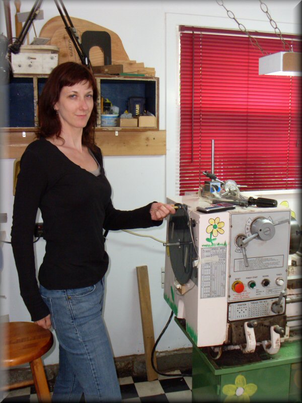
Anyway, anything is possible with enough planning and preparation. I decided to wind the coils on my lathe, because it's tailor-made for workholding and turning things. Even on the slowest speed, though, the motor goes too fast for comfortable control, so i enlisted the help of my sister lovely assistant Amy to turn the spindle at a more reasonable speed. I'm kind of digging the idea of the "verbal speed control" that responds to commands like "Ok, go forward one turn," "slower," "faster," and "ACK!! STOPSTOPSTOP!!" Plus, it's nice to have someone else to talk to in the shop. (Thanks, Amy!)
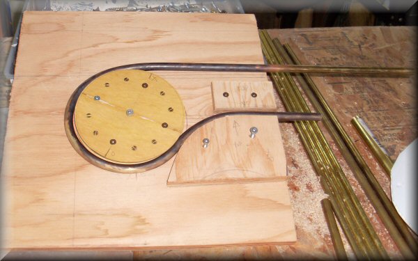
The manual crank handle is mounted on the indexing disk i made for working on bagpipe chanters.
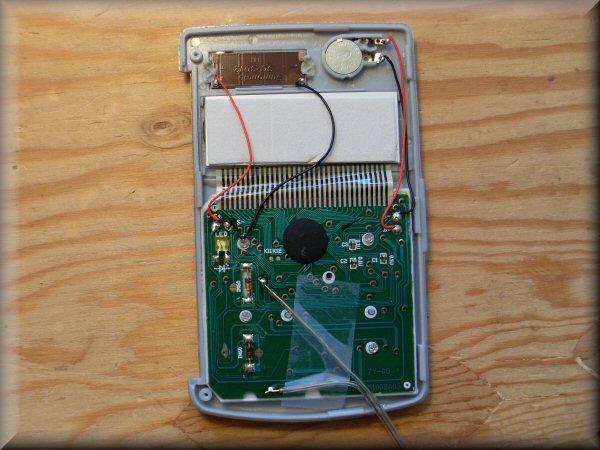
In order to keep track of the number of turns, i adapted a cheap calculator to serve as a counter. I located the circuit contacts for the "=" button, and attached a pair of wires, so it could be "pressed" remotely. (On most calculators, you can press "+ 1 =", and then repeating the "=" will repeat the +1 operation, acting as a counter.)
The other end of the wire goes to a magnetic reed switch, which will activate when a magnet passes close. So, i mounted a magnet on the indexing disk pictured above, and the calculator now counts revolutions of the crank handle. I got the idea from other coil winders out there on the internet, and it works very well.
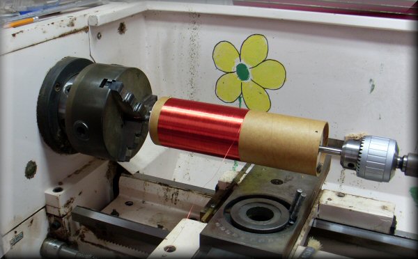
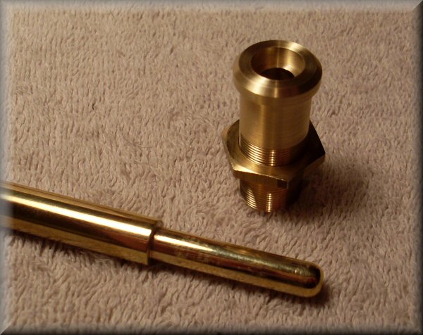
In progress. The coil form is phenolic tube, made for model rocketry. It's surprisingly nice to work with - even though it's paper based, it cuts and drills very neatly. It's supported and driven by disks i turned from plywood to precisely fit the inside of the tube. The one at the tailstock end rides on ball bearings so it doesn't drag.
The wire going on this coil is 32 AWG magnet wire, which is about .008" thick. That's the width of a few human hairs.
When winding, i'm hunched over the rotating form, using a guitar pick to push the newest turn tight up against the already-wound wire. We had several glitches and hiccups, occasionally having to "rewind" a handful of turns, but overall it went pretty smoothly...
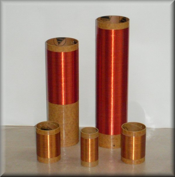
The finished coil set. (For reference, the tallest form is 12.5" high and 3.1" diameter.)
There's 600, 1200, and 3 x 150 turns, totalling about 1/3 of a mile of wire!
I've coated them with clear polyurethane to help protect the windings.
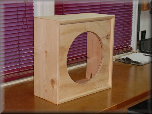
Here's my speaker cabinet "in the white." Like the classic RCA instruments, this theremin has its own amplifier built in, and just needs a plain speaker in a box. I've got a (somewhat vintage) 12" full-range speaker to go in here.
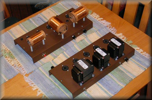
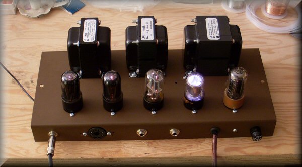
Here are the two chassis with all the hardware installed: transformers, tube sockets, terminal strips, jacks and controls. The lower section will house the power supply and audio amplifier, the upper one (with the coils) is for the theremin oscillator circuitry.
Ready to start soldering!
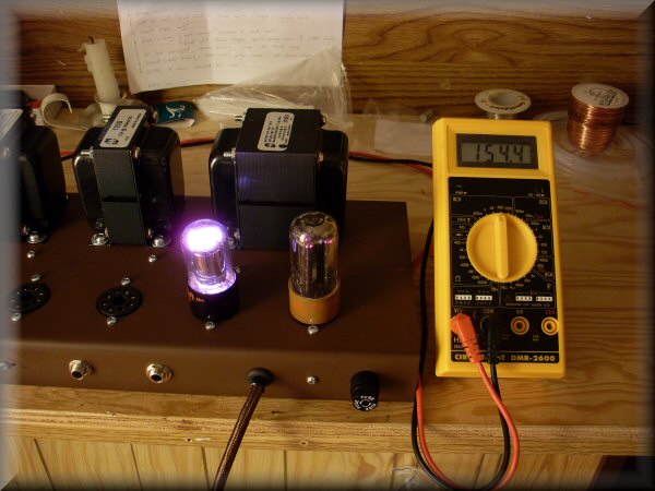
Ok, stage one is complete! I've got the power supply wired up. The two tubes installed are the 5y3 (rectifier) and the 0d3 (voltage regulator). The 0d3 isn't technically a vacuum tube - it's filled with some kind of gas that ionizes and somehow regulates the output voltage to 150v. Just as important, it glows that pretty pinky purply colour.
I've been looking forward to seeing this tube light up, so this is Very Satisfying Indeed! Yay!
(Note also the classy antique-style cloth covered power wire.)
The lower chassis is complete and working well!
I hooked up a CD player (the wire out the left end) and loaded up one of my favourite Russian pop albums. It worked the first time! The amp gets good and loud without distorting, and the circuitry is dead quiet - no hiss or 60-cycle hum, even with the volume turned right up.
The power switch, volume knob, and mute switch are on the front (the far side in the photo). The jacks on the rear are for speaker and "line out" connections. The 8-pin socket is to connect the upper (oscillator) chassis: wires for power and ground, and for getting the theremin signal in to the amplifier.
All the tubes are NOS ("new old stock"); the two power supply tubes are US made, and the rest are Soviet-era Russian. All made during the cold war, from both sides together at last!
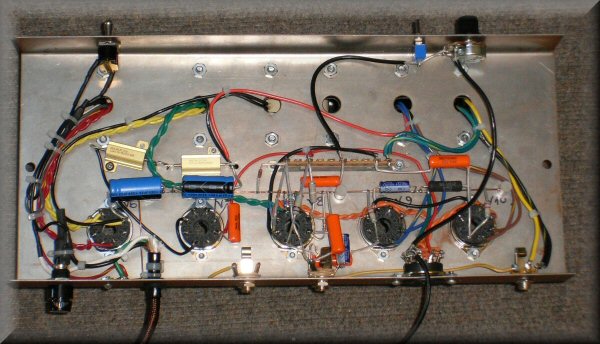
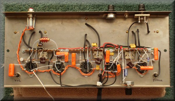
Here's the underside. I was getting a lot of guidance from other builders' progress photos, but you have to make some stuff up as you go. I'm pretty happy with the wiring job here - naturally since it works so well, but it's fairly organized and tidy. As much as i could make it, anyway.
The power switch is an old one i've had in my junk box for years. It looks kind of bulbous, and feels fantastic. They don't make them like this anymore! I have no idea where it came from originally, but it turns out i've been saving it for exactly this project. I had to disassemble it to clean decades of gunge off the contacts inside, and it's found a new life in this theremin...
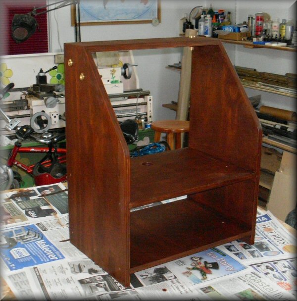
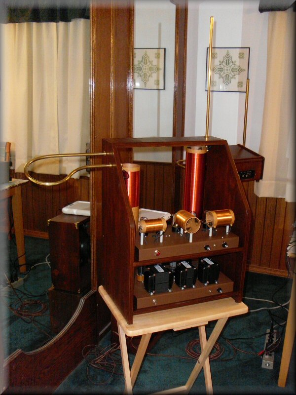
In order to properly test and calibrate the circuitry, the physical geometry of the antennas & coils needs to be in place. So here is a "prototyping" cabinet, made of plywood.
I'm planning to just leave the instrument in this cabinet and play it this way until i can get a "proper" cabinet made (presumably by someone with better woodworking skills than myself.) In the meantime, it will look very cool with all the gleaming coils and tubes on proud display. In fact, this theremin should be very much at home at the Victoria Steampunk Expo next month!
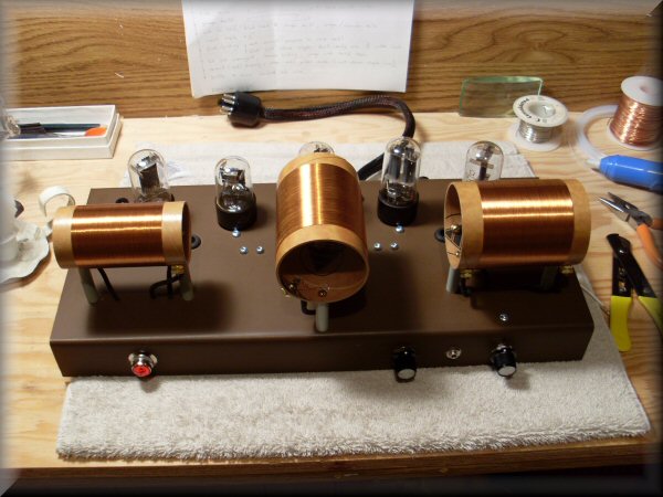
Here's the upper (oscillator) chassis out of the instrument. The middle knob & jack are for a pitch-preview function which i have yet to build & install. I object on principle to junking up this elegant tube theremin with a solid-state pitch-preview amp, but if i want this to be my ultimate lifetime theremin, it should be as all-singing and all-dancing as much as possible. Since the jack was mentioned on the schematic, i decided to implement it if i could.
Another nice feature is the top access holes for the trimmer capacitors - you can see the grommets peeking out from behind the left and right coils.
All these tubes are 1970s/80s Soviet NOS.
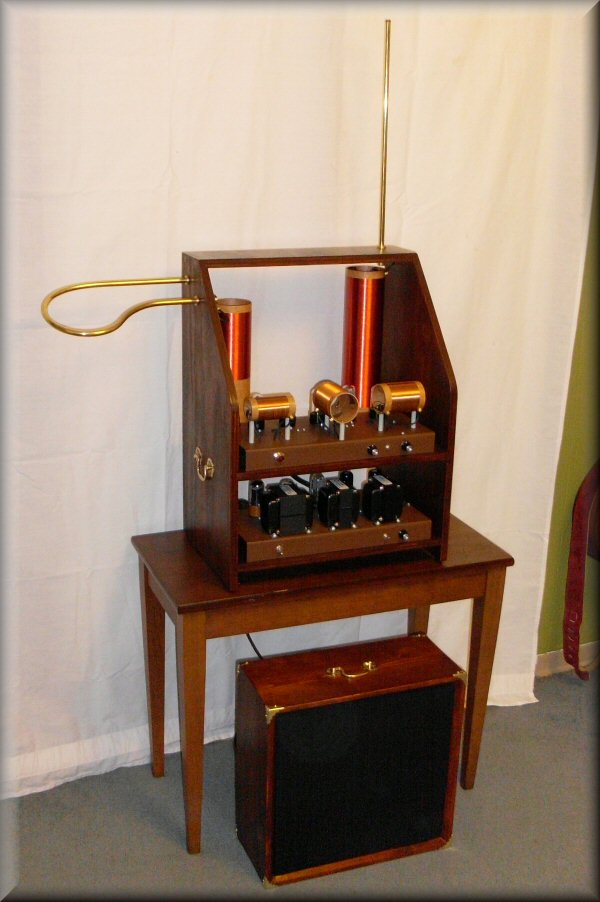
Here's the completed instrument in its open cabinet, and the finished speaker cabinet.
It's playing fairly well. There's a few stray harmonics i'm still trying to chase down, but the overall sound is quite lovely! I'll post a sound sample in the next little while...
Enormous THANKS are due to Mark Keppinger and everybody on the "kepptheremins" Yahoo! group for the inspiration and support, and putting up with my boneheaded questions. I've learned a lot while doing this project, and when i read back through my build diary and the questions i've had, i realize just how much i've learned. Which is great. So thanks!
Update: I've learned that this instrument is #16 on the (in)formal registry of this Keppinger-designed theremin model. So it's a pretty small and exclusive club, and a very special instrument.